
Overview
Every day the Sun delivers more energy to the surface of the Earth in one hour than all the people on Earth use in an entire year. Why don’t we use more solar energy? It’s renewable, and carbon-free, and plants have used solar energy to power global ecosystems for millions of years. What if we could use energy more like plants do? Turns out we can!
Introduction
Using materials like iodine, blackberry juice, and a few specialized components, students will create a working solar cell that mimics the process of photosynthesis.
Grade Level
6-8, 9-12
Learning Objectives
Students will
- build a working solar cell
- measure the voltage of the solar cell
- connect cells in series to power an electric device
Lesson Format
In School: This is a lab activity. Ideally students will work in small groups to assemble the cells, then connect all the cells to power a device.
Time Required
This activity requires about 90 minutes of lab time. Teachers can prep some of the materials ahead to allow students to move more quickly.
Additional discussion and analysis will require an additional class period.
Standards
NGSS:
- Planning and Carrying Out Investigations
- Analyzing and Interpreting Data
- PS3.A: Definitions of Energy
- ESS3.D: Global Climate Change
- ETS1: Engineering Design
- ETS2.B: Influence of Engineering, Technology, Science on Society & the Natural World
- Scale, Proportion & Quantity
- Energy & Matter
Credits & Contact Info
Dr. Alexandra Moore
Paleontological Research Institution, 1259 Trumansburg Rd., Ithaca NY 14850
moore@priweb.org
Instructions & Materials
Resources
- Video | In the Greenhouse #17 | DIY Solar Energy: Photosynthetic Solar Cells
- Instructor and Student Handouts are all available from the Cornell Center for Materials Research
Materials
The Cornell University Center for Materials Research (CCMR) offers an extensive lending library of student kits for NGSS-aligned K-12 science lessons in Chemistry, Physics, and Earth Sciences. Materials for the Dye-Sensitized Solar Cell activity here come from the CCMR Lending Library. The kit includes most of the required materials (exceptions below) in sufficient quantity for your class size. The kits are shipped, free, to your school. Lesson plans and handouts are available to download. This activity is available in both English and Spanish. Request your kits here.
Teachers will also need to provide:
- Small beakers for mixing
- Small graduated cylinders
- Balance/scale
- Blackberries, raspberries, or blueberries (do not use strawberries)
- Paper towels
- Lighter/Matches
- Hot plate or similar to heat & sinter the slides (see instructions)
- Small electrical devices to use with the solar cells (mini lightbulbs, fans, etc)
- Lab coats/aprons/smocks for students. This activity involves three highly pigmented materials that can stain clothing if spilled
Instructions
Download the handouts.
Familiarize yourself with the materials in the Solar Cell kit, then assemble a cell yourself. The CCMR instructional video that walks you through this process is extremely helpful:
Decide if you want to prep any of the materials ahead of time for your students. Preparing the TiO₂ solution and sintering it to the slide is probably the most fussy and time-consuming step, and could easily be done ahead.
The student handouts that come with this activity include some basic questions for the students; consider if you need to modify the handouts & questions for your class. Background, context, and helpful tips and tricks for the experiment are provided in the next section of this web page, below.
Background & Extensions
Overview
In order to power human communities in the 21st century we need to integrate solar power into every facet of our lives. Solar energy is abundant - everywhere - even in places that we don't think of as warm and sunny. And new generations of solar cells take advantage of new techniques that make them more efficient, more affordable, and more useful in a wide variety of applications, for example, solar cells that are thin and flexible and cells that work in low light conditions. Another approach that is becoming more common is to integrate solar power into the design of a building, an idea called Building-Integrated Photovoltaics (BIPV). Dye-sensitized solar cells (DSSCs) like those that we will build in this activity are already in use in BIPV applications. The center image of the banner on these web pages is the atrium of the conference center in Lausanne, Switzerland where DSSCs are used as "stained glass" in the windows.
Electricity Basics
Electricity arises from the charged particles in atoms - the protons and electrons. The electricity that we interact with every day is charge in motion. We define that motion as the electrical current. Here are two common descriptions of current:
I = V / R
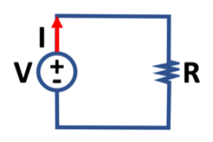
where I is the current, which is proportional to V, the voltage. The constant of proportionality is R, the resistance, which is a characteristic of the material that carries the current, and here we see that this is an inverse proportion. The graphic on the right shows the relationship of these parameters in the context of a simple electrical circuit.
Voltage is a gradient. A gradient is a set of unequal conditions, and gradients make things move. Here are three topographic gradients, where the elevation of one end of the surface is different—unequal—from the other:
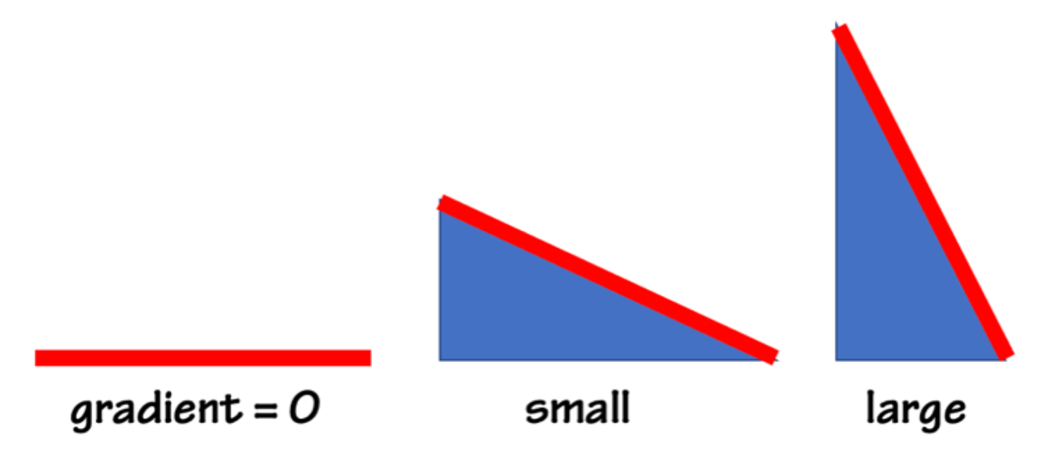
When conditions are equal the gradient is zero, and nothing moves. The larger the gradient the larger the motion. An electrical gradient is often called electrical potential difference, or voltage.
In this experiment the solar cell that we build provides the gradient to move charges and create a current. We will test whether we've succeeded by measuring the voltage.
Units for Electricity
⚛︎ The SI unit of current is the ampere, or amp (A). At its most fundamental level an amp is 6x10¹⁸ electrons in motion per second.
⚛︎ The unit of voltage is the volt (V), with SI base units V = kg∙m²∙s⁻³∙A⁻¹
⚛︎ The unit of resistance is the ohm (Ω), defined when one volt produces a current of one amp, with SI base units Ω = kg∙m²∙s⁻³∙A⁻².
In everyday life we often think of electricity in combination with energy.
⚛︎ The SI unit of energy is the joule (J). A joule is defined as the amount of work done when a force of 1 newton displaces a mass of 1 kilogram by a distance of 1 meter; thus determining the base units of the joule, J = kg∙m²∙s⁻².
Energy and work are both measured in joules. And what about watts?
⚛︎ A watt (W) is the unit of power, equal to one joule per second: W=J∙s⁻¹ = kg∙m²∙s⁻³
Notice that the SI units of watts and volts allow us to express a direct relationship between electricity and energy: V = W/A. We can re-arrange that to express, power, in watts, as W = V∙A. So power is equal to current multiplied by voltage.
At its simplest, a semiconductor is a material that has electrical conductive properties that fall between those of a conductor and an insulator. What is missing from that definition, however, is what makes semiconductors so useful. We can design and control the conductive properties of a semiconductor by changing its chemistry or structure. For example, we can make semiconductors that send current more easily in one direction than the other, show variable resistance, or are sensitive to light or heat. Adding impurities to a crystalline silicon wafer makes it sensitive to light - the basis of many photovoltaic cells. In the case of the dye-sensitized solar cell, we created a useful semiconductor by adding raspberry juice to the TiO₂ film. Because of their wide range of applications, semiconductors are literally everywhere.
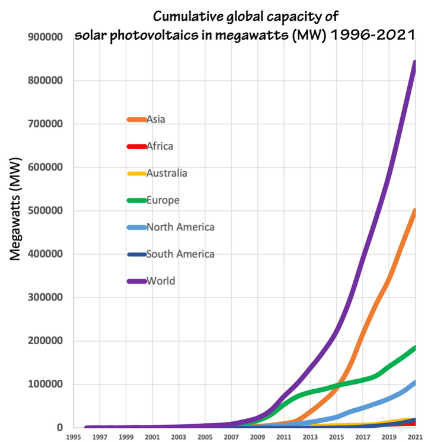
Figure 1: Cumulative global capacity of solar photovoltaics, 1996-2021. Figure by Alexandra Moore for PRI's Earth@Home project (CC BY-NC-SA 4.0 license), with data from Our World in Data
Photovoltaic cells are built with light-sensitive semiconductors that convert energy from light into electrical energy. Sunlight excites electrons within the material that create an electrical current. Solar cells have been used in applications in space for many decades, beginning with the launch of the NASA Vanguard satellite in 1958. Here on Earth most solar panels are made from crystalline silicon wafers doped with boron or gallium impurities. They are about 15-20% efficient in converting solar power into electrical power. In the last 25 years (1995-2021) global solar power installation has grown exponentially (literally exponentially, not a figure of speech; Figure 1). The concurrent expansion of electronic devices in every aspect of life coupled with increasing awareness of the climate crisis is fueling development of new types of solar cells designed for myriad new applications (see "Take it Beyond the Classroom," below).
Practical Tips & Tricks for DSSC Assembly
The berry juice and iodine liquids used in this activity will seriously stain clothing (the soot from carbon-coating with candles can be messy too). You and your students should take every precaution to avoid spills and stains. Smocks/labcoats/aprons are a must. Lab trays to keep the bottles in during the solar cell assembly are a good idea so that if spills occur they are contained.
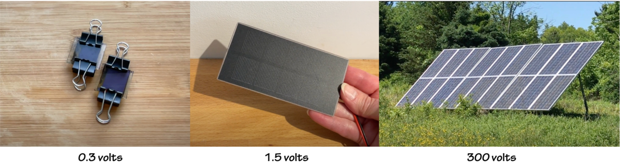
These little solar cells don't need to be perfect to work. If the TiO₂ coating is chipped or scratched, or if the carbon coating is uneven, or the iodine fill is uneven, the cell will still create a voltage. You can expect the voltage to range from 0.1 - 0.5V for each cell.
In order to create a voltage in sunlight the dye-sensitized solar cells need to be "sunny side up." Make sure the students understand which side of their solar cells are photo-active. Here the electrode, the purple side, where we applied the TiO₂ and the berry juice should face the Sun. When connecting the multimeter to measure voltage, connect the black (-) cable to the TiO₂ electrode and the red (+) to the carbon-coated counter-electrode.
Ideas for powering devices with your DSSCs are in the Data section, below.
Data Collection: Quantify the Results
You can use the multimeter to measure the voltage that each individual cell produces. More interesting than a number on a meter is to use the solar cells to power a small device. To do that, you'll have to connect the cells together in order to create enough power, as these are very small cells, and both the voltage and current are very low.
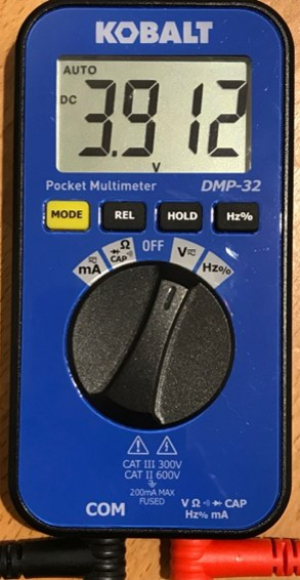
digital multimeters
The kits from CCMR include a digital multimeter to allow you to analyze the results of your work. If you're not familiar with a multimeter, look at the options available to you around the edge of the dial. On the multimeter shown here you can measure current (mA), resistance (Ω), voltage (V) and the frequency of an alternating current (Hz). If the cables aren't already attached to the meter, plug the black cable (-) into the COM terminal and the red (+) into the other. We'll begin with the dial set to voltage. Note that there are two kinds of current, direct (DC) or alternating (AC). The solar cells create a direct current, so make sure you measure the voltage with DC selected (there might be a Mode button for you to toggle, shown here, or the DC voltage may be indicated with a straight bar, as opposed to a squiggle for AC). To measure current, look for the setting labeled A, for amp, or mA for milliamps. The photo, right, shows a multimeter with the dial set to V. The display reads 3.912 volts. DC current is indicated by the small "DC" just left of the large number 3 on the display, and the units of voltage (V) are shown at the bottom of the screen.
Powering a Device with DSSCs Part 1: Find a Device
The DSSCs in this activity are tiny. Even hooked together they can't do a lot of work, therefore, you'll need to do some work ahead of time to make sure you've got a small enough device that will actually power up with your students' cells. If you watched the video linked at the top of this page you saw that we were able to power a little digital music box with four cells operating in full sunlight. The music box is a nice solution because, unlike a small lamp, it's easy to know that it is working when you're outside in bright sunlight. The music box is also the lowest-power device that we've found, and it has worked every time we've done this experiment (squeaks at 0.9V and plays normally at 1.2V). The device in the video is available from Vernier.
If your class has assembled 5, 6, or more, cells you may also be able to power an LED lamp. Light emitting diodes are incredibly efficient; they emit a lot of light at very low power and don't give off waste heat the way old incandescent light bulbs do. Being diodes, however, means that they are little one-way streets, they only let current flow one way. Just like the DSSCs themselves, you have to connect them with the right polarity for them to work. Each lamp has a long wire and a short wire; the long wire is the anode and connects to the positive terminal of a battery, while the short wire is the cathode, and connects to negative. You can test this by sliding a 3V button battery in between the two leads; one way lights up, the other doesn't. LEDs also have a color-dependent threshold voltage that is required for them to illuminate. You can see in Figure 2 that red has the lowest threshold and will light up at 1.8V, while white is the highest, requiring 4.0V. If your solar cell array is producing 2.0 volts it will light up a red LED but not a blue one. Blue light is higher energy (shorter wavelength) than red light and so it takes more electrical potential—voltage—to make blue light than red. LEDs don't "like" too much current, so use small batteries—button, AAA, AA—to test your LEDs (for more on LEDs, see here).
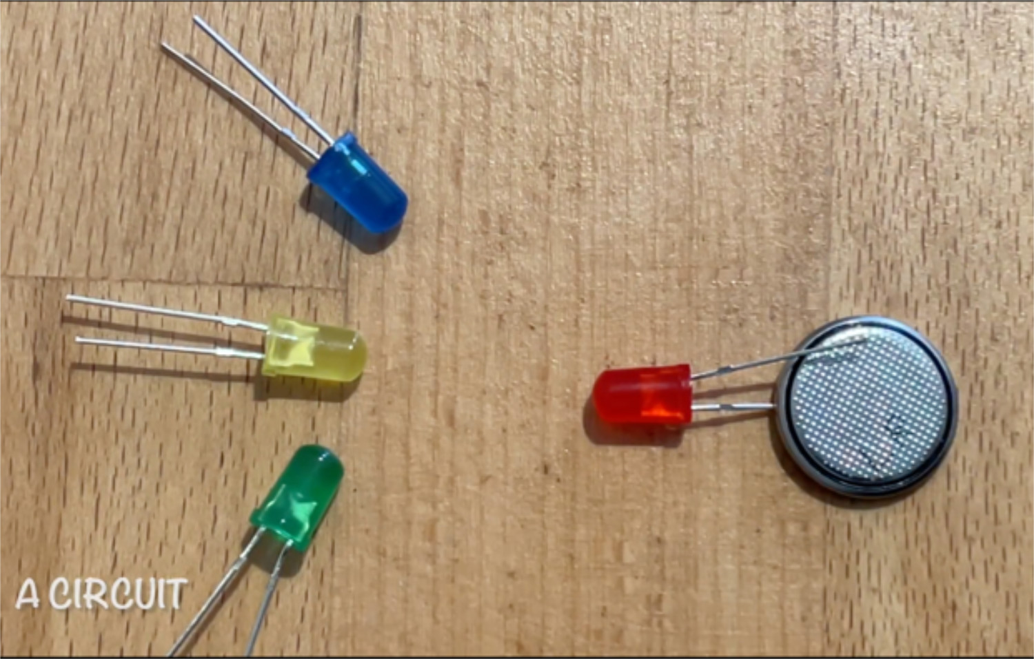
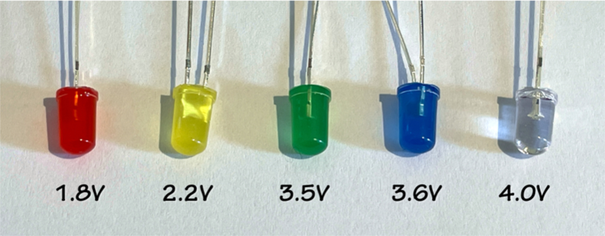
Figure 2: Five colored LED lamps and the threshold voltage for each.
Powering a Device with DSSCs Part 2: Connect the Cells in Series
To power a device we need to create a circuit; a closed loop connecting our power modules and the device. To take advantage of all of our DSSCs and increase the power output we connect the elements in series, creating a circular chain that results in the sum of the voltages of each individual cell.
Note: you will get more voltage from the cells outdoors in full Sun, but they will also work indoors under a bright lamp (or lamps); typical fluorescent ceiling lights may not be bright enough. If you will be going outdoors, it might be helpful to tape or mount the DSSCs to a tray/board/sturdy cardboard so that you can easily carry them outside and connect them with alligator clip wires.
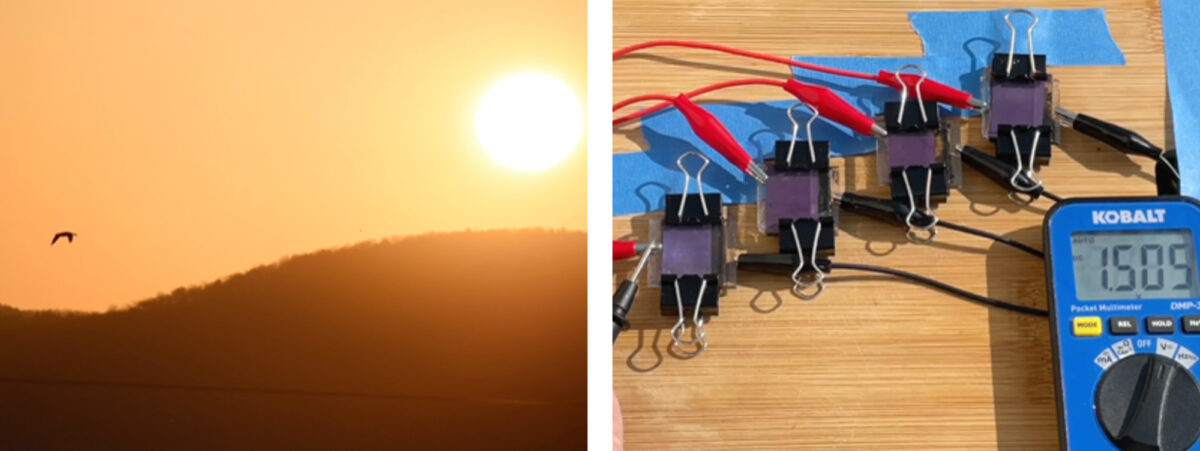
Figure 3 shows how to connect three DSSCs in series with a multimeter. The cells are arranged head-to-tail (positive-to-negative) and connected with clip wires. The two end cells are connected to the multimeter. The multimeter display shows the sum of the voltages, in this case, three 0.4V cells totaling 1.2V. To add a lamp or music box, replace the multimeter in the circuit with the device. If you've got enough voltage, try some different devices or multiple devices to see what works!
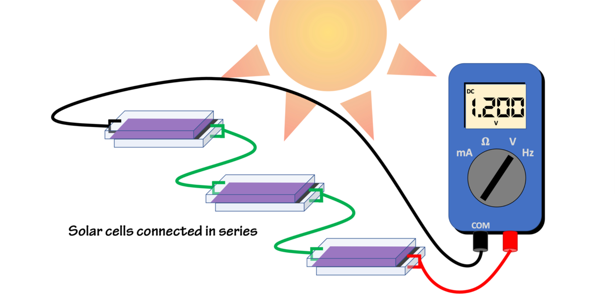
Figure 3: Connect the negative lead (black) to the TiO₂ electrode, and the positive lead (red) to the carbon-coated counter-electrode. To increase the total voltage, connect the solar cells in series; head-to-tail, aka, positive-to-negative. The voltage will be the sum of the individual cells. Figure by Alexandra Moore for PRI's Earth@Home project (CC BY-NC-SA 4.0 license)
Take it Beyond the Classroom
Increasingly large arrays of conventional solar cells deployed for utility-scale electrical power have fueled the increase in PV capacity seen in Figure 1. Other technologies and novel applications also have the potential to change how we power large and small spaces, as well as large and small devices. Dye-sensitized solar cells, like the ones that we assembled in this activity are a technology that works well in low-light conditions. Another low-light PV system is the perovskite solar cell. These techniques are being studied as alternatives to disposable batteries in a wide variety of applications. Another area of research is the development of thin and flexible solar cells made from semiconducting ink that could be used almost anywhere.
These new technologies, along with standard PV cells, are all seeing applications in Building-Integrated Photovoltaics (BIPV). A BIPV design includes PV cells as part of the structure, skin, or decor of a building.
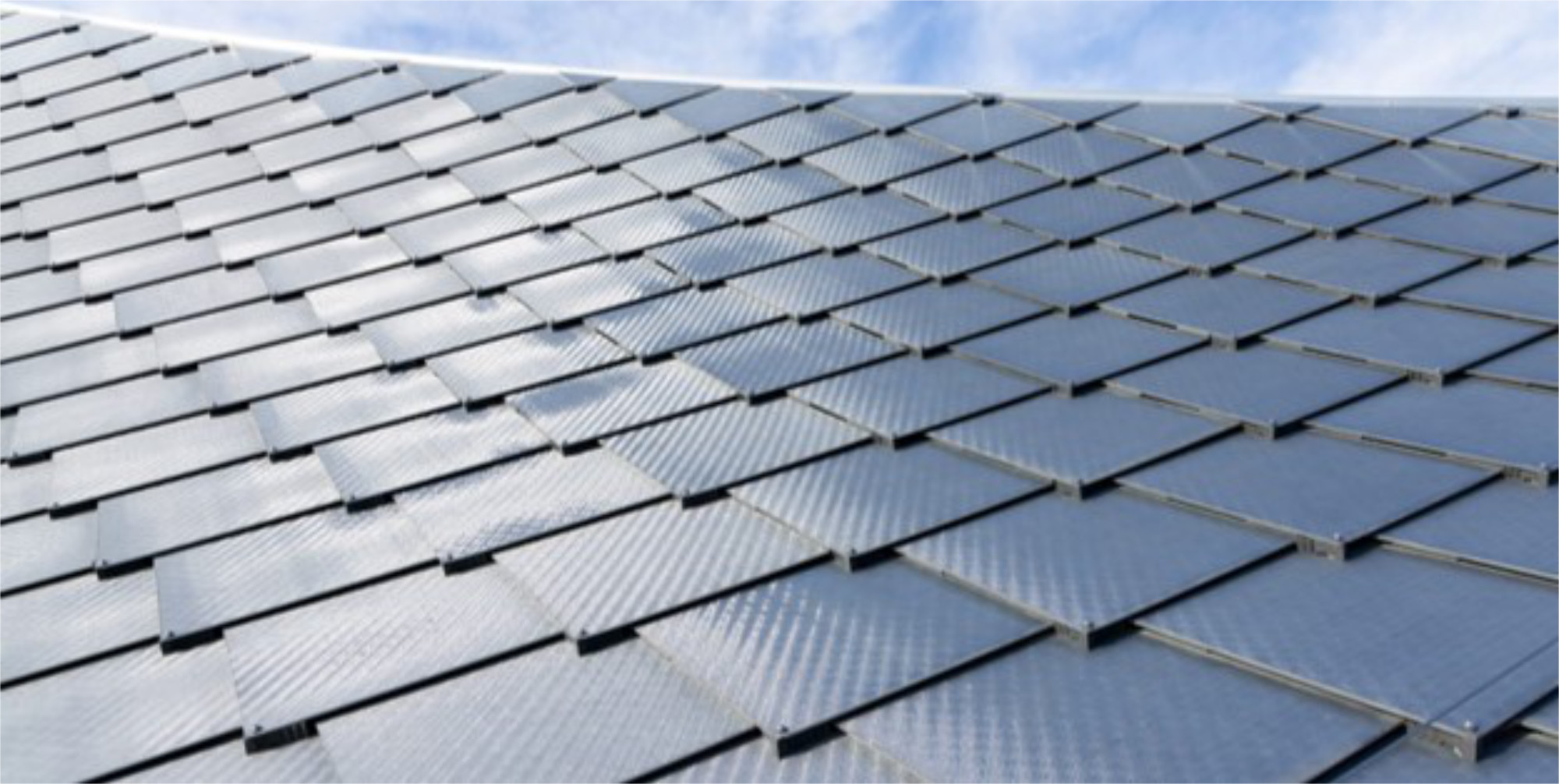
Figure 4: Example of BIPV, a close-up look at the "Dragonskin" solar roof tiles on the Google campus in California. The solar roof produces ~40% of the building's electricity. Photo by Iwan Baan for Dezeen.com

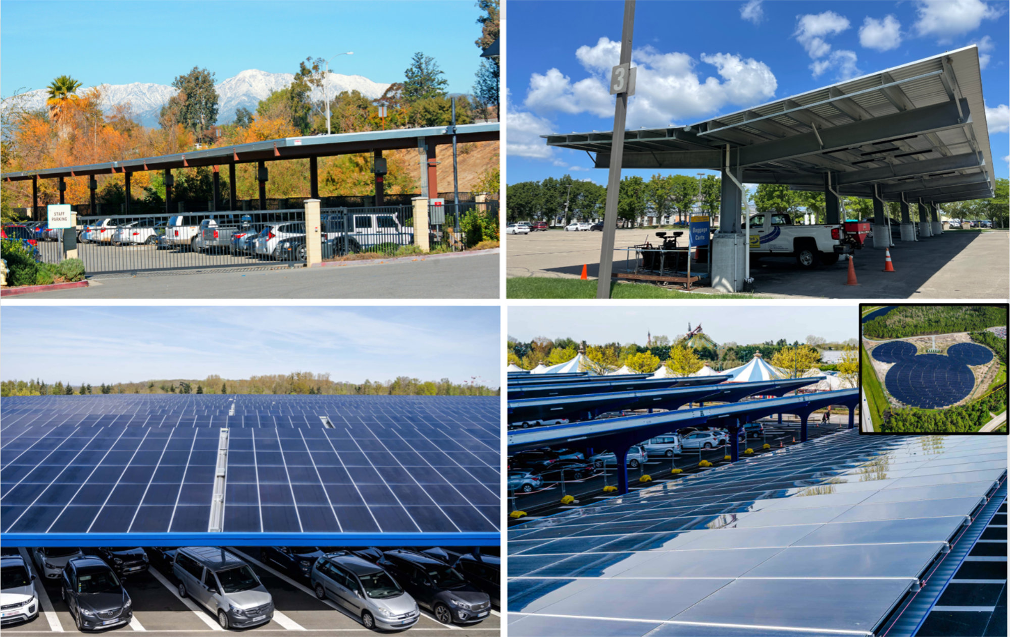
Another widely-used BIPV application isn't nearly as beautiful as the two examples above, but has enormous potential impact; BIPV parking lots. Solar sunshades over parking lots provide both power to the community and shade for parked cars, and unlike solar farms built on open space they take advantage of space already dedicated to a different purpose. The solar sunshades at Disneyland Paris (below) are the largest solar installation in the Paris region. As of July 1, 2023, French law requires all outdoor car parks to have photovoltaic shade structures on at least half of their surface.
Solar Stained Glass
There are currently two methods used to create colorful power-generating glass elements in buildings. The first is to embed opaque PV cells as part of the design within a colored glass matrix (Figure 7). The second is to design an array of translucent PV cells, like the DSSCs that we made in this activity (Figures 8 & 9).
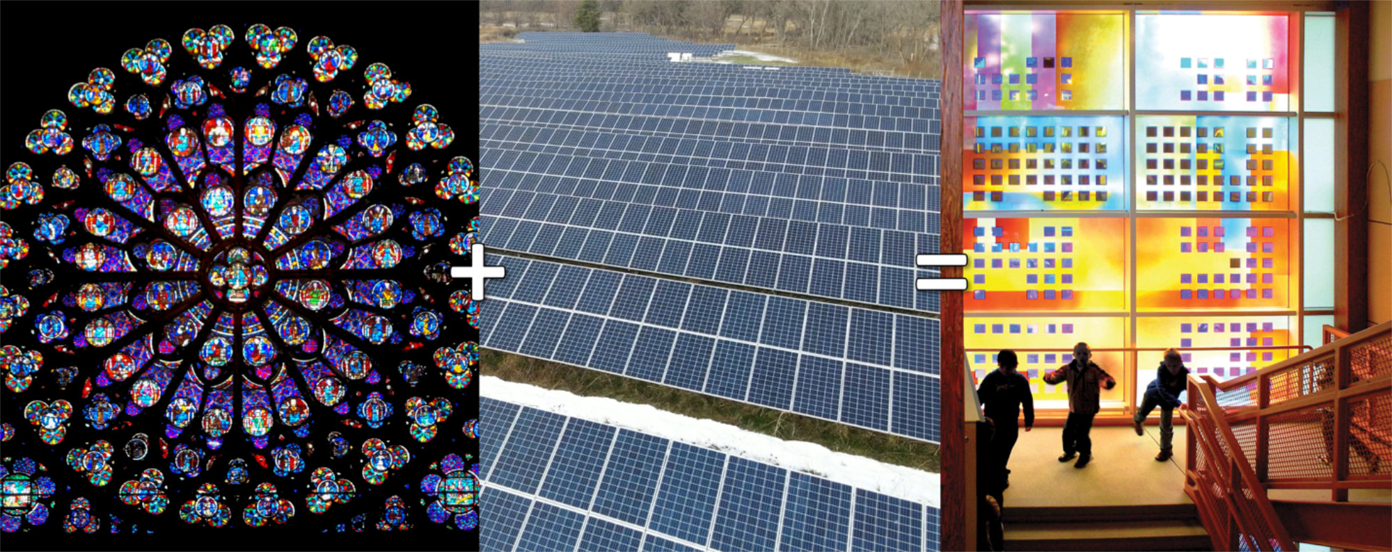
Figure 7: An example of Solar Stained Glass (right). Canadian artist Sarah Hall embedded conventional silicon solar cells in stained glass to create the power-generating Science of Light window in the main stairwell of Grass Valley Elementary School in Camas, WA. Credits: photo of cathedral stained glass by Alexandra Moore, used with permission; photo of solar array by Alexandra Moore, used with permission; photo of solar stained glass by CODAworx.
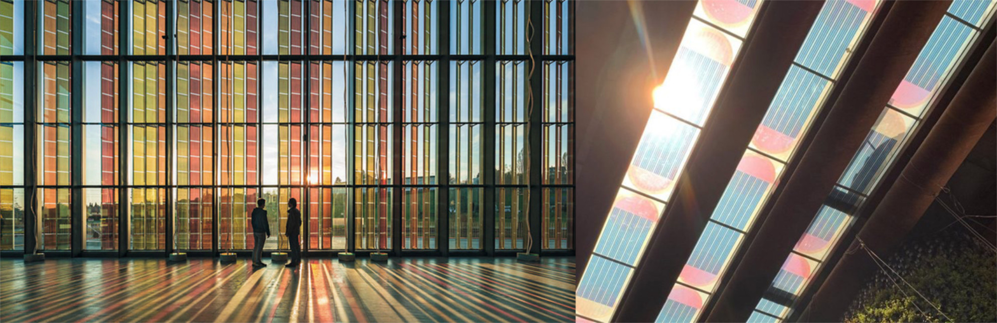
Figure 8: Left; A larger view of the 300m2 DSSC panel array at the SwissTech conference center of the Ecole polytechnique fédérale de Lausanne, Switzerland. Right; Solar stained glass in the ceiling of the Dutch Pavilion at Expo 2020, Dubai. Credits: left photo by Roland Herzog, EPFL, from Science; right photo by V8 Architects via dezeen.com.
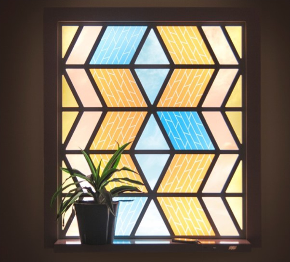
Finally, imaging plugging your phone or computer into a window! That's what Dutch glass artist Marjan van Aubel had in mind when she designed the Current Window (Figure 9). Here she uses DSSCs with TiO2 and organic pigments to make a stained glass window that includes a USB charger built into the windowsill.
➢ What ideas could you and your students come up with to create something beautiful and useful with solar energy?